...
On each subject the goal is to gather a large sample to allow a breakthrough in our understanding. This is only made possible thanks to the improved sensitivity of PIONIER combined with its excellent operational efficiency.
Instrument description
...
...
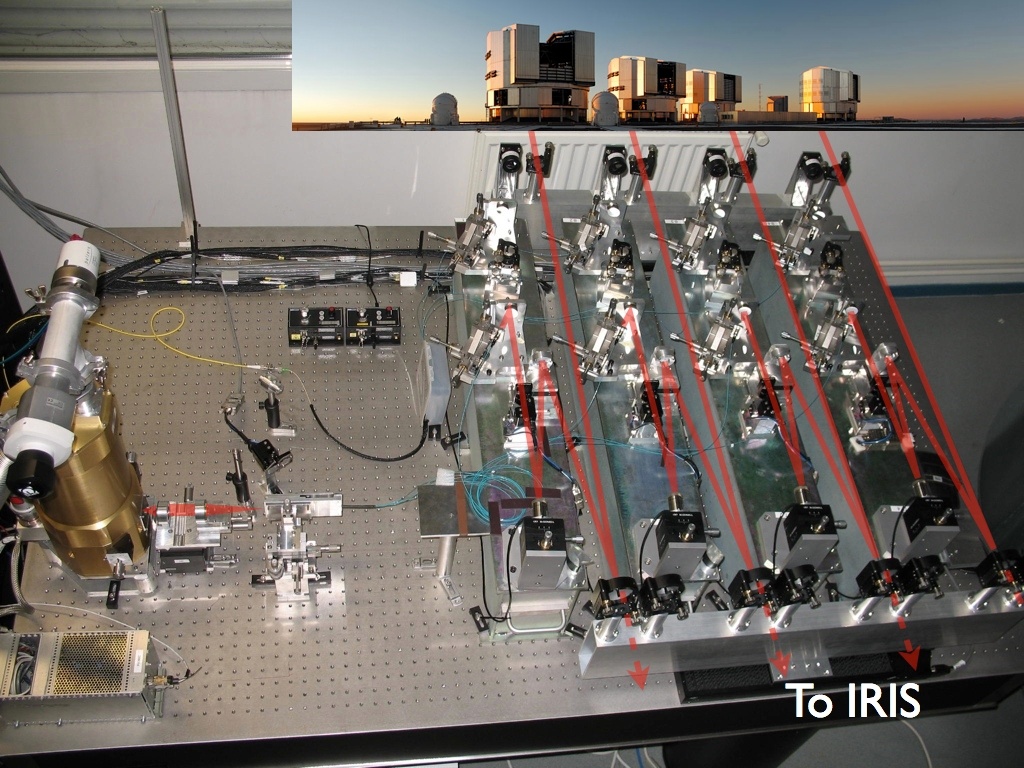
PIONIER has four independent arms that allow the incoming VLTI beams to be injected in fibers. Each arm is equipped tip/tilt and piezo-OPD correction plus shutter. The 4 single-mode fibers guide the light to an integrated optics combiner (IOBC). The IOBC ouput is imaged, through a double doublet + prism onto the detector. The 24 dispersed IOBC outputs are read by the IOTA/IONIC3 PICNIC detector with modified electronics and software.
...
The Instrument Software Package is subdivided into the following standard INS software modules: ICS, DCS, OS, MS. Observing templates are executed using the standard ESO BOB tool. Dialog between PIONIER and VLTI (e.g delay lines) is achieved through the VLTI Interferometer Supervisor Software. The architecture has been split into 2 parts; detector system and instrument control system. It is similar to a standard VLTI instrument with an instrument WS, an ICS LCU and a DCS WS, with dedicated tip/tilt and OPD correction facilities. The instrument WS is a standard Linux PC platform supported by the VLT Software. The detector WS is an industrial Linux PC platform equipped with a PCI-7300A board used to generate clock signals and to acquire detector data. It is running under the VLT Software. The instrument LCU is an Embedded PC from BECKHOFF with EtherCAT/fieldbus terminals for I/O.
...
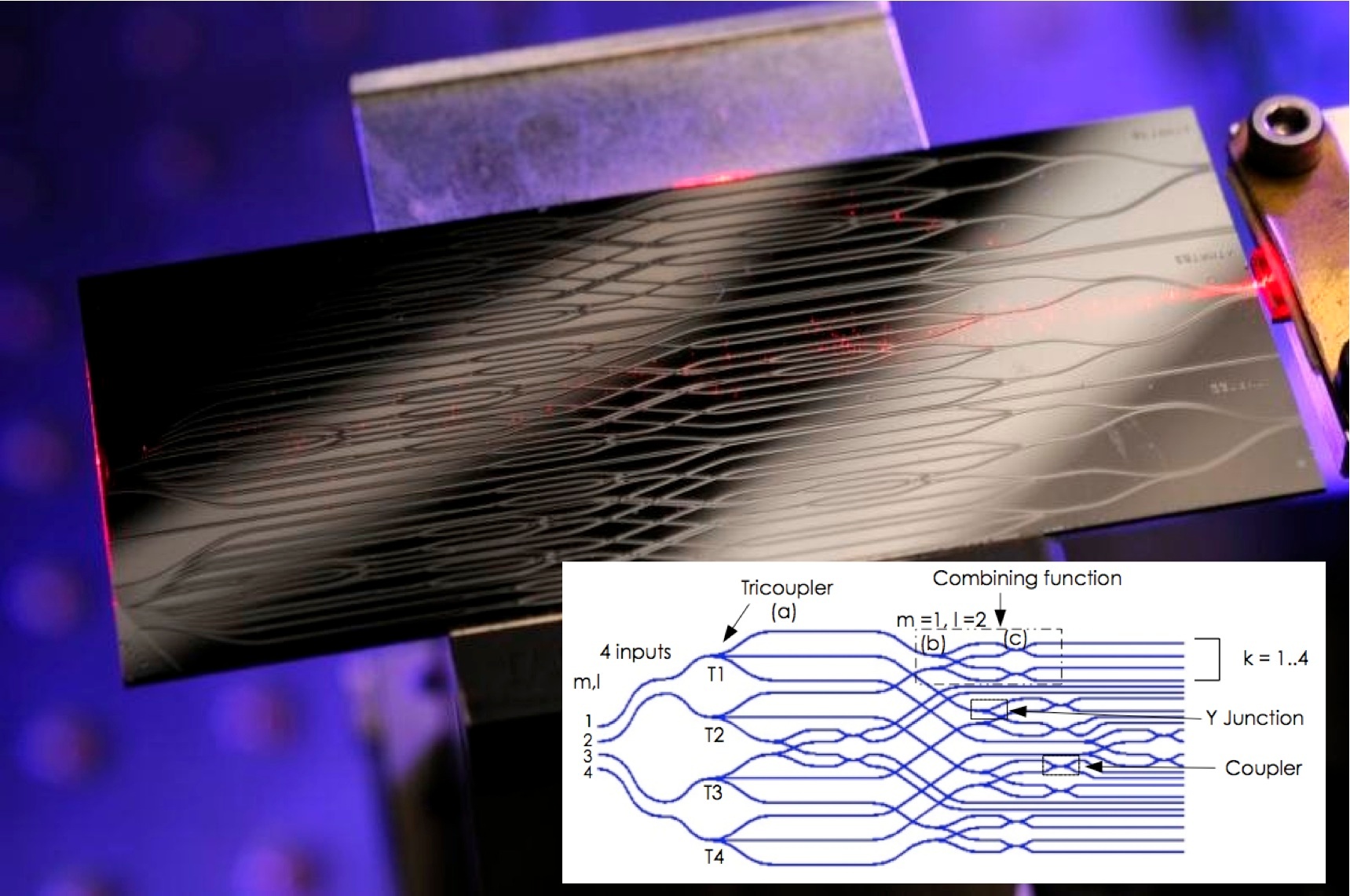
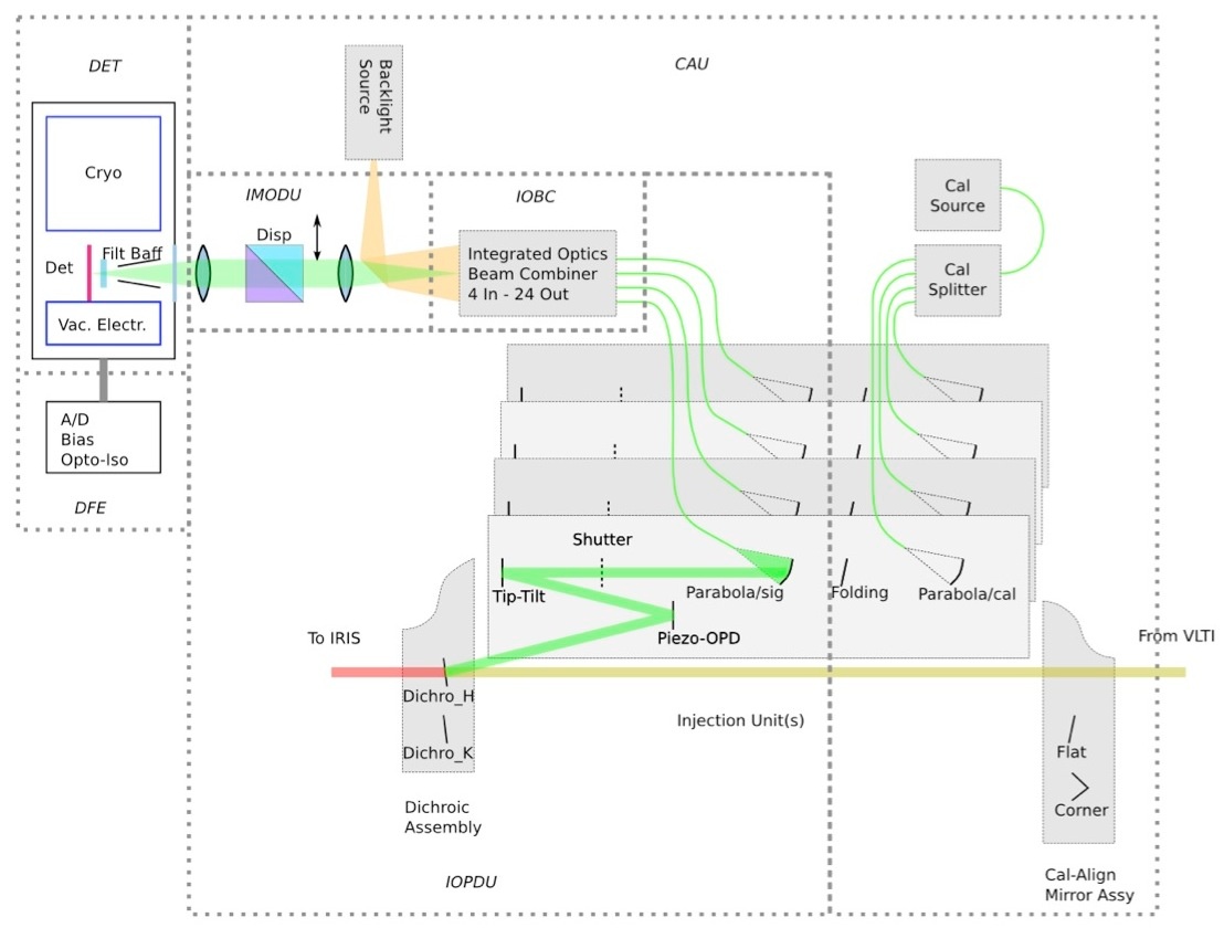
Left: Fig. 2. PIONIER conceptual scheme. The Injection and Optical Delay Unit (IOPDU) is responsible for the injection of the four beams (either from CAU or from VLTI) in the single mode fibers. It also implements the OPD modulation, the tip-tilt correction and the polarization control. The Integrated Optics Beam Combiner (IOBC) recombines the four beams into 24 interferometric outputs in a pairwise scheme. These outputs are then imaged, and eventually spectrally dispersed, by the Imaging Optics and Dispersion Unit (IMODU) on the detector (DET). The aim of the Calibration and Alignment Unit (CAU) is to provide four interferometric beams that match the size and angle of the VLTI beams. Right: Picture of the optical chip and schematic of the IOBC layout realized by CEA-LETI in collaboration with LAOG (contact: pierre.labeye@cea.fr)